Rtd Thermocouple Wiring Diagram

Rj11 Socket Wiring Diagram Australia, How to punch down an RJ11 Telephone Jack, 6.36 MB, 04:38, 387,634, CableSupply.com, 2009-08-05T00:16:07.000000Z, 19, Rj11 Socket Wiring Diagram Australia | Computacion, Redes de computadoras, Computadoras, www.pinterest.com.mx, 728 x 783, jpeg, rj11 wiring rj45 diagram cable ethernet usb jack pinout adapter cat5 female male convert using rs485 cat wires code socket, 20, rj11-socket-wiring-diagram-australia, Anime Arts
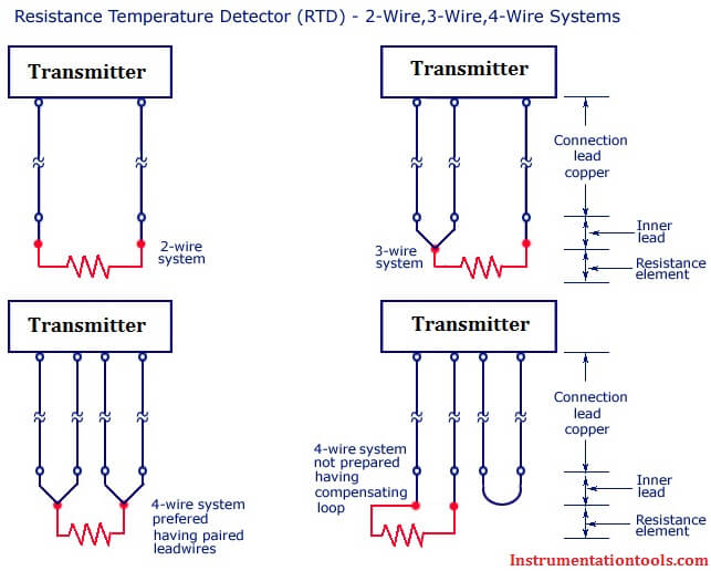
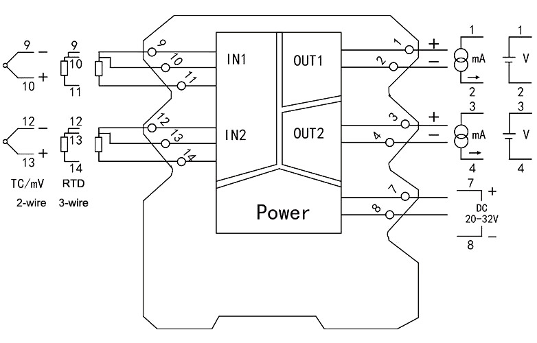
See the table for a list of supported thermocouple input types. Configure the module to do the linearization necessary for rtd inputs. See the table for a list of supported input types. L1 and l3 carry the measuring current while l2 acts only as a potential lead.
In this article we will learn about rtd thermocouple, rtd thermocouple wiring diagram, rtd thermocouple cost. An overview the thermocouple is one of the most basic sensors available. It is made up of two dissimilar metal wires that are connected near the measurement. Connection diagrams for rtd temperature probes and thermocouples to ensure uniform wiring of all temperature probes, jumo manufactures rtd temperature probes and thermocouples according to the jumo house standard. All wiring instructions required for installation are found in the chart below: • do not wire more than 2 conductors on any terminal. • when you connect or disconnect the removable terminal block (rtb) with field side power applied, an electrical arc can occur. This could cause an explosion in hazardous location Rtds are generally more accurate than thermocouples.
Rtd Pt100 3 Wire Wiring Diagram | Free Wiring Diagram

Difference Between 2 wire RTD, 3 wire RTD, and 4 wire RTD's

Thermocouple/RTD signal conditioner, Analog Output 4-20mA/0-10mA/0-5V | ATO.com

Gallery Of 3 Wire thermocouple Wiring Diagram Sample

Thermocouple Wiring Diagram Download

Precision Thermocouple Temperature Measur - Maxim Integrated

Rtd Pt100 3 Wire Wiring Diagram | Free Wiring Diagram

Get 3 Wire Rtd Wiring Diagram Download

RTD and thermocouple circuits with millivolt calculations Worksheet - Instrumentation and

Thermocouple vs rtd online
